TESTING A GAUGE Click to jump to this section.
THERMAL-TYPE GAUGE
Beetles were first sold with electric fuel gauges beginning with the 1968 model year. Karmann Ghias and Buses had them even before this.
The gauge used on the Beetle from '68 onward is a thermally-actuated design. It is not a new concept; Ford used gauges similar to this as early as the 1930's and it probably goes back even further.
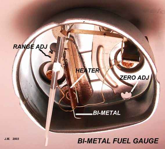
Here's the basic concept: the float in the fuel tank drives a rheostat (variable resistance). The rheostat varies the current flowing into the fuel gauge on the dash. Inside the gauge, a tiny heating element responds to the rheostat current. When fuel level is high, current is at a maximum and the heater gets hottest. The heater is wound around a small bi-metal strip; as the heater warms up, the strip bends or "warps".
The picture above shows the gauge as it is mounted in the speedo housing. The lower end of the bi-metal strip is fixed. The upper end will move left or right, depending on the heater temperature.
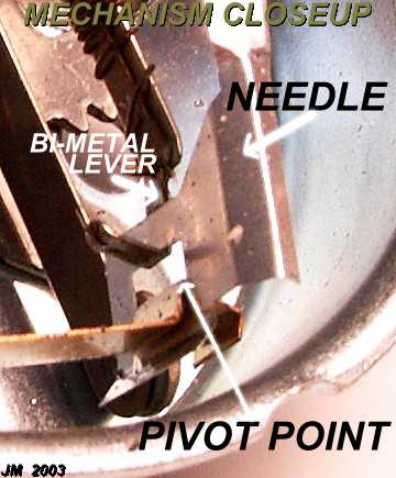 This
photo was taken with the gauge "upside-down". The pivot point is where the
needle is attached. The bi-metal lever has a "hook" which pushes or pulls
the needle. Because of the short distance between the hook and the anchor point
for the needle, a small movement of the bi-metal strip results in a very big travel
of the needle.
This
photo was taken with the gauge "upside-down". The pivot point is where the
needle is attached. The bi-metal lever has a "hook" which pushes or pulls
the needle. Because of the short distance between the hook and the anchor point
for the needle, a small movement of the bi-metal strip results in a very big travel
of the needle.
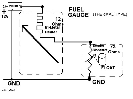
Shown below is the circuit diagram.
When the tank is Empty, the rheostat has roughly 73 Ohms resistance. Only a small
current flows through the heater as a result. This is just enough to keep
the needle at the lowest mark on the dial. As the float rises, more and more current
flows, driving the needle upward. When Full, the rheostat has approximately
10 Ohms resistance and maximum current flows to the gauge.
DAMPING- This type of gauge is inherently heavily damped. During cornering, fuel sloshes about and the float bobs up and down, varying the current to the gauge. But it takes a fairly long time for the bi-metal to respond to the current change (1 or 2 seconds). This delay averages out the variations due to float bobbing.
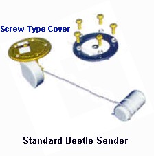
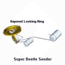
FLOATS- Below are the 2 styles of floats
used on Beetles.
Due to the odd tank configuration on Super Beetles, 2 floats are used to move the
rheostat at different rates during the transition in shape.
VOLTAGE REGULATION
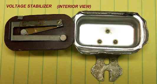
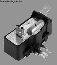
Because of the sensitivity of the heater/bi-metal design, it is very important that the input voltage to the gauge be constant. Voltage regulation is accomplished by a very simple, yet effective, design. Shown below are the exterior and interior views of the voltage stabilizer or "vibrator", as it is often called.
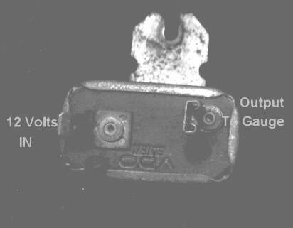
The vibrator is screwed to the back of the speedo housing. It is very important that this screw connection is well grounded or else the vibrator won't operate properly. The connection from the vibrator output may be made to either side of the gauge, depending on how the vibrator is mounted.
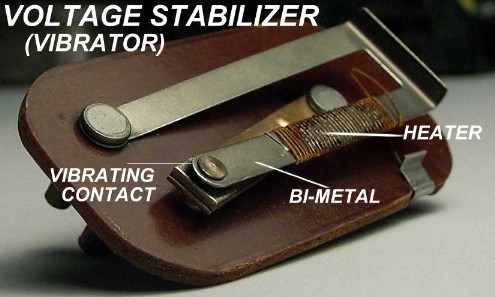
The design incorporates the same type of bi-metal strip and heater as found inside the gauge. But here it has a different purpose. 12V from the battery heats up the heater element and warms the strip. The thermal mass is small and the strip responds very rapidly. As soon as it begins to move, the strip causes the contact points to open. This breaks the circuit and the current ceases. Now, the strip begins to cool off and bends back to its original shape, closing the contact. This repeats, over and over. The result is a series of pulses, each with a voltage of 12V. When the pulses are fed to the gauge, the heater element in the gauge averages the pulses out.
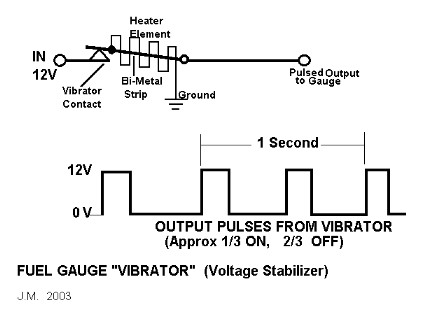
The closer the pulses are together or of longer duration, the hotter the heater in the gauge will get. By accurately controlling the pulses, the stabilizer has the effect of regulating the voltage (here, we're talking about RMS or "effective" voltage). Suppose that battery voltage goes up (as when the generator increases output). The heater in the stabilizer will heat up more rapidly and open the contact points sooner. The result will be shorter pulses of 12V sent to the gauge. The opposite happens when the battery voltage goes lower.
It all sounds quite crude and un-reliable but, in fact, it does work rather well and at low cost.
MORE MODERN REGULATOR
Whether driven by cost or reliability I don't know, but the vibrator stabiliser has been replaced by a Zener diode shunt regulator design. 12V input is fed thru a series resistance in the form of a small incandescent lamp to a 5.2V Zener diode. The lamp provides some regulation in itself since incandescent filaments vary in resistance dramatically as they heat up. If the 12V supply increases (as when battery is charging), the lamp gets slightly brighter and its resistance goes up, decreasing the output voltage. The Zener then performs the remainder of fine regulation required.
The internal circuit looks like this:
Some experiments have been done to determine the relationship between tank fuel level and sender resistance.
This graph shows tank volume in Liters vs. sender Ohms:
and this graph shows sender Ohms vs. fuel gauge needle position:
For testing a fuel gauge, it may be helpful to obtain a 100 Ohm potentiometer (rheostat) and mark off the shaft/knob position for various resistances and use that to simulate the tank sender.
(Thanks to Rasheed Reda for providing helpful info about the Zener regulator and sender resistance.)
BALANCE COIL GAUGE
No heaters or bi-metal in this type of gauge. Rather a meter movement, like that in a voltmeter or ammeter is used to detect the current from the sending unit rheostat. A small permanent magnet sets up a field which interacts with magnetism produced by coil windings inside the meter. A voltmeter usually only has one such winding; our fuel gauge has 2 windings as shown schematically below.
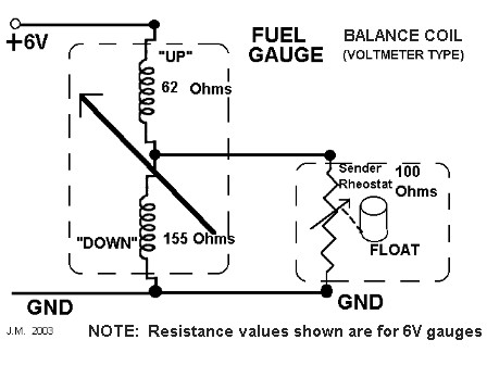
The coil winding resistances and sender resistance are set so that when the float is at the bottom of its travel, the magnetism from one coil perfectly balances out the other.
(NOTE: Not all gauges were identical in design; winding resistances varied considerably in production.)
Now, as the float moves upward, resistance decreases and more current is pulled through the "UP" coil. At the same time, current is "robbed" away from the "DOWN" coil. The net effect is to cause the needle to move upscale.
No voltage regulation is required with this type of gauge because of the cancelling effect of the 2 coils. For example, a rise in input voltage will cause more current to flow in the "UP" coil, but it will also cause more current in the "DOWN" coil. The 2 cancel each other. This gauge is quite stable over a reasonable voltage swing.
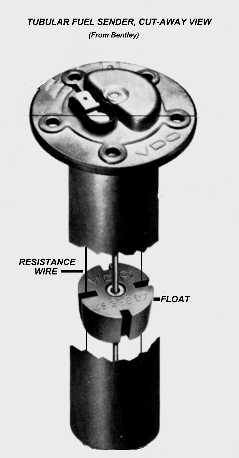
This tubular sender is the type commonly used with the balance-coil gauge. The 2 thin wires are made of resistance material wire. As the float moves up and down, it makes contact between the 2 wires. Upward movement means less resistance in the circuit.
DAMPING- This gauge is not inherently damped since it has no thermal mass to rely on. Without damping of some kind, the needle would fluctuate wildly as the car rounded corners and fuel sloshed about. To overcome this, small holes are drilled in the outer tube. If tank level suddenly changes, it takes several seconds for the fuel to flow in and out of the holes and for the float to respond.
![]() The Balance Coil type
of gauge was used on Buses up until the '73 models (thru VIN 2132138900).
Late '73 and later Buses used the thermal type of gauge with a bayonet mount sender
(single float).
The Balance Coil type
of gauge was used on Buses up until the '73 models (thru VIN 2132138900).
Late '73 and later Buses used the thermal type of gauge with a bayonet mount sender
(single float).
Karmann Ghias used Balance Coil gauges until late in the '73 model year (VIN 1432621518), then they switched to thermal type until the end of production.
All Type 3 cars (fastback/squareback) used the Balance Coil gauge.
![]() TESTING
THE GAUGE Often it is hard to determine whether the gauge or the sender
is the cause of problems. Do these 2 easy tests:
TESTING
THE GAUGE Often it is hard to determine whether the gauge or the sender
is the cause of problems. Do these 2 easy tests:
Pull the wire off the sender. The gauge should go to EMPTY.
Take the sender wire and ground it (Ground it to chassis, not the tank).
The gauge should go to FULL.
If it passes both these tests, the gauge is good and any problems are in the sender.
NOTE: Later senders have 2 wires; one is the wire to the gauge, the other is a ground wire. On these senders, ground is always Brown; the sender wire may be either Black or Yellow (or even Green). Make sure that the Brown wire actually goes to a grounding stab somewhere on the chassis.
There is no absolute test for the vibrator (thermal gauges), but a pretty good check can be made by connecting a voltmeter (old fashioned analog type) or a small 12V test lamp from ground to the vibrator output terminal (where it connects to the gauge). The voltmeter should bob up and down several times a second. If it does, the vibrator is probably good. They rarely go bad and failure is usually complete.
If a gauge is intermittent, check the tightness of the 2 hex nuts on the back of the gauge; they have a habit of loosening on the thermal gauges. Intermittent gauge operation can also be caused by poor contact at the fuse supplying this circuit.
![]()